Memory
Overview
The memory hierarchy refers to the various storage devices used in a computer, arranged from expensive and fast to cheap and slow. A typical hierarchy looks like:
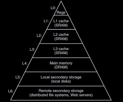
Storage Devices
A storage device is called volatile if they lose their information when supply voltage is turned off. Nonvolatile memories retain their information even when powered off.
RAM
Random access memory (RAM) comes in two varieties - static and dynamic. SRAM is both faster and more expensive than DRAM.
Static
Static RAM (SRAM) is primarily used for cache memories. SRAM stores a bit in a bistable memory cell implemented as a six-transistor circuit. Provided it has power, it can stay indefinitely in either of two different voltage configurations, i.e. states.
Dynamic
Dynamic RAM (DRAM) is primarily used for main memory. DRAM stores a bit in a cell consisting of a capacitor and a single access transistor. DRAM also leaks - a cell loses its charge within a time period of around 10 to 100 milliseconds.
ROM
Read only memory (ROM) is the historical term used to describe nonvolatile memories. Note this is a misnomer - many ROMs can be written to. ROMs are distinguished by the number of times they can be written to and the mechanism used to write them. Some examples include:
- Programmable ROM (PROM)
- Written to exactly once.
- Erasable Programmable ROM (EPROM)
- Written to on the order of 1,000 times.
- Uses ultraviolet light to clear cells to zero and a separate device to write ones.
- Electrically Erasable PROM (EEPROM)
- Written to on the order of 100,000 times.
- Can be re-programmed in place.
Flash
Flash is a nonvolatile storage device based on EEPROMs.
Solid State Disks
A solid state disk (SSD) is based on flash memory. An SSD package consists of one or more flash memory chips and a flash translation layer responsible for translating requests for logical blocks into accesses of the underlying physical device.
Flash memory consists of a sequence of blocks, where each block consists of a number of pages. A page can only be written to after the entire block to which it belongs has been erased. Wear-leveling logic is used to maximize the lifetime of each block by spreading erasures evenly across all blocks.
Hard Disk Drives
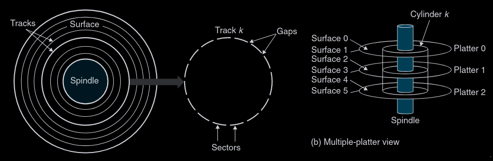
Hard disk drives (HDDs) are constructed with one or more platters stacked on top of each other and encased in a sealed package. Each platter consists of two surfaces coated with magnetic recording material. A rotating spindle in the center of the platters rotates them at a fixed rotational rate.
Each surface consists of a collection of concentric rings called tracks. Each track is further partitioned into a collection of sectors, each of which contains an equal number of data bits. Sectors are separated by gaps where no data bits are stored; gaps store formatting bits used to identify sectors.
Metrics
There exist a few common metrics used to evaluate the capacity of an HDD:
- Recording density (bits/in). The number of bits in a 1-inch segment of a track.
- Track density (tracks/in). The number of tracks in a 1-inch segment of the radius extending from the center of the platter.
- Areal density (bits/in
). The product of recording density and track density.
To maximize areal density, multiple zone recording partitions the set of cylinders into disjoint subsets called recording zones. Each track in each cylinder in a zone has the same number of sectors, which is determined by the number of sectors in the innermost track of the zone.
Operation
Disks read and write bits stored on the magnetic surface using a read/write head connected to the end of an actuator arm. By moving the arm back and forth along its radial axias, the drive can position the head over any track on the surface (a mechanical motion known as a seek).
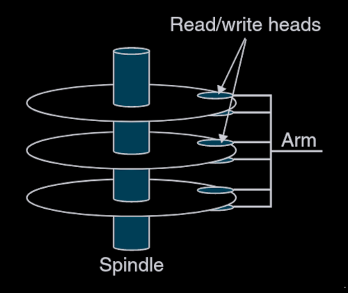
There is one read/write head for each surface, all connected to a single arm. At any point in time, all heads are positioned on the same cylinder.
Disks read and write data in sector-size blocks. The access time for a sector has three main components:
- Seek time. The time required to move the actuator arm so the read/write heads are positioned correctly.
- Rotational latency. The time required to rotate the disk until the first bit of the desired sector is under the head.
- Transfer time. The time required to read or write the contents of a sector.
Logical Disk Blocks
Modern disks hide their geometry, instead presenting to the OS a sequence of